Magnetic Effects of Current
Contents
Introduction
A static charge produces only an electric field while a moving charge is capable of creating both an electric field and a magnetic field. This phenomenon has been proved from the Oersted’s experiment. Thus, a current-carrying conductor is capable of producing a magnetic field around it. Also, an external magnetic field can exert a force on it.
Biot-Savart Law
The Biot-Savart law states as follows:
The magnetic field intensity produced by a small element \(dl\) currying current \(I\) at a distance of \(r\) from it is
\[\begin{align} \vec{dB} &= \dfrac{\mu_{0} \cdot I \cdot \vec{dl} \times \vec{r}}{4\pi \cdot {|r|}^3} \\\\ \left|\vec{dB}\right| &= \dfrac{\mu_{0} \cdot I \cdot dl \cdot \sin \theta}{4\pi \cdot {|r|}^2}, \end{align} \]
where \(\mu_{0}\) is the magnetic permeability of free space equal to \(4\pi \times {10}^{-7}\) and \(\theta\) is the angle between \(\vec{dl}\) and \(\vec{r}.\)
The SI unit of magnetic field intensity is Tesla (T).
Finding the direction of the magnetic field intensity:
- Right-hand thumb rule: The direction of the magnetic field due to a current-carrying conduction at any point can be obtained by pointing the thumb of your right hand in the direction of the flow of current and curling your other fingers towards the point at which the direction of the magnetic field has to be found. The direction in which your fingers proceed at the instant your fingers reach the required point is the direction of the magnetic field.
Magnetic field intensity on the axis of a current-carrying ring:
Consider a ring of radius \(R\) carrying a current of \(I\) in the clockwise direction. We have to find the magnetic intensity due to this ring at a point which is at a distance of \(x’\) units from the center on the axis of the ring.
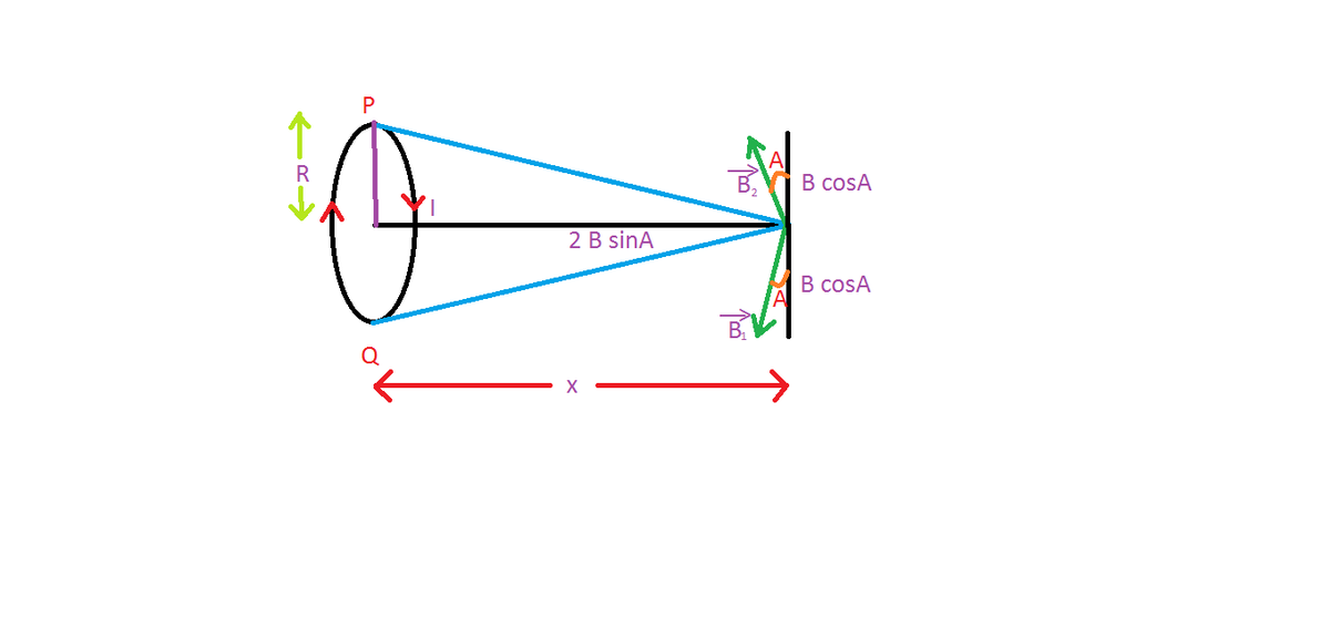
Take a point \(P\) on the ring. The magnetic field due to this point is \(\vec{B_1},\) as shown. Take another point \(Q\) on the ring diametrically opposite to \(P.\) The magnetic field due to \(Q\) is \(\vec{B_2}.\) Clearly, \(\Big|\vec{B_1}\Big| = \Big|\vec{B_2}\Big|.\) As we can observe, the components of the magnetic fields perpendicular to the axis are canceled out by their counterparts while those parallel to the axis are added up. Due to a point length \(dl\) at \(P,\) the horizontal component of the magnetic field using Biot-Savart law is as follows:
\[\begin{align} dB & = \dfrac{\mu_{0} \cdot I \cdot \sin A\, dl}{4 \pi (x^2 \ + \ R^2)} \\ \\ \int_{0}^{B} dB & = \int_{0}^{2\pi R} \dfrac{\mu_{0} \cdot I \cdot R\, dl}{4 \pi {(x^2 \ + \ R^2)}^{3/2}} \qquad \left( \text{since } \sin A = \dfrac{R}{\sqrt{R^2 + x^2}} \right) \\ \\ \Rightarrow B & = \boxed{\dfrac{\mu_{0}I R^2}{2 { \big( R^2 + x^2 \big) }^{3/2}}}. \end{align}\]
- So, we see that for obtaining magnetic field at the center of the ring. Plug in \(x = 0\) and we get \({\color{blue}{B = \frac{\mu_{0} I}{2 R}}}.\)
- Furthermore, if the ring has \(N\) turns, then simply multiply the result with \(N,\) i.e. \(B = \frac{\mu_{0} \cdot N \cdot I}{2 R}.\)
- Since finding the magnetic field at the center of a ring only included adding components of magnetic field due to infinite number of infinitesimally small pieces, we should be able to conclude that the magnetic field at the center of a circular segment of wire subtending an angle of \(\theta\) at the center is \(\frac{\mu_{0} I}{2 R} \times \frac{\theta}{2\pi}.\)
Magnetic field due to a finite wire:
Consider a finite, current-carrying wire \(AB\) such that a current of \(I\) flows from \(B\) to \(A.\) According to the right-hand thumb rule, every point on this wire creates a magnetic field of intensity \(dB\) inside the plane of the paper. Let \(PE = r\) units.
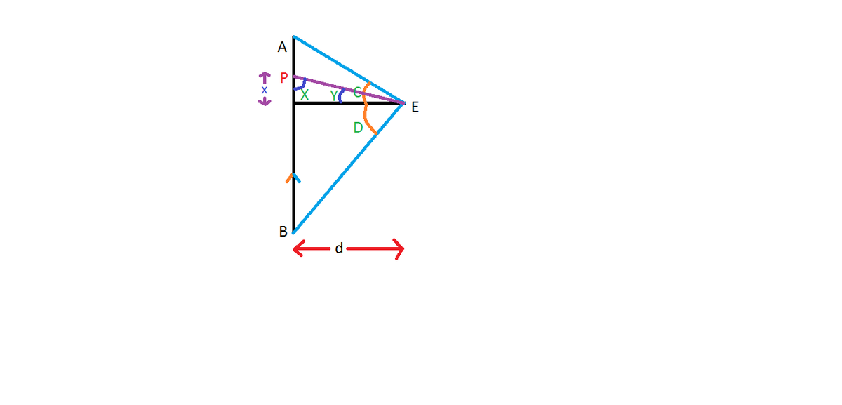
Due to a small length \(dx\) at point \(P,\) as shown, the magnetic field at \(E\) is given by
\[\begin{align} dB & = \dfrac{\mu_{0}\cdot I\cdot \sin X \, dx}{4\pi r^2}\\ \\ \int dB & = \int \dfrac{\mu_{0} \cdot I \cdot \sin X\, dx}{4\pi r^2}\\ \\ x &= d \tan Y \implies dx = d \big(\sec Y\big)^2 dY\\ \\ r &= d \sec Y,\ X = \dfrac{\pi}{2} – Y \\ \\ B & = \dfrac{\mu_{0} I}{4\pi d} \int_{-D}^{C} \cos Y\, dY\\ \\ & = \boxed{\dfrac{\mu_{0} \cdot I}{4\pi d} \big( \sin C + \sin D \big)}. \end{align}\]
From this result, we can deduce that for an infinitely long wire, \(C = D = \frac{\pi}{2}.\)
Therefore, \(B = \frac{\mu_{0} I}{2\pi d}.\)
Magnetic field intensity due to a solenoid at a point on its axis:
Consider a cross-section of a solenoid of \(N\) turns, as shown. We can consider a solenoid to be made up of an infinite number of rings of infinitesimally small width. As proven above, the magnetic field due to a ring at a point on its axis is \(\dfrac{\mu_{0}I R^2}{2 { \left( R^2 + y^2 \right) }^{3/2}}\).
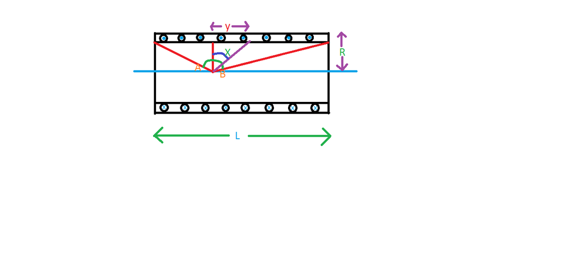
Consider a small circular cross-section of negligible width at a distance of \(y\) from the given point. The number of turns in this cross-section is \(\frac{N}{L} dy:\)
\[\begin{align} dB & = \dfrac{\mu_{0} \cdot I \cdot N \cdot R^2\, dy}{2 L { \left( R^2 + y^2 \right) }^{3/2}} \\ \\ \int dB & = \int \dfrac{\mu_{0} \cdot I \cdot N \cdot R^2\, dy}{2 L{ \left( R^2 + y^2 \right) }^{3/2}}\\ \\ y &= R \tan X \implies dy = R \big(\sec X\big)^2 dX \\ \\ B & = \dfrac{\mu_{0} \cdot I \cdot N }{2 L} \int_{-A}^{B} \cos X\, dX \\ \\ & = \boxed{\dfrac{\mu_{0}I N}{2 L} \big( \sin A + \sin B \big)}. \end{align}\]
Clearly, from the above result for an infinitely long solenoid, at any point on the axis \(A = B = \frac{\pi}{2}.\)
Therefore, \(B = \frac{\mu_{0} \cdot N \cdot I}{L} = \mu_{0} N' I,\) where \(N'\) is the number of turns per unit length.

Consider a circular ring conductor connected to a battery as shown.
Find the magnetic field intensity at the center of the ring.
The current would distribute in the two semi-circles as shown.Now, due to the current in the upper semi-circle, the magnetic field at the center is inside the plane of the screen (away from us). Similarly, due to the lower semi-circle, the magnetic field at the center is of equal magnitude but outside the plane of the screen (towards us).
So, they get cancelled out and the net magnetic field at the center is \(\boxed{\text{zero}}.\)
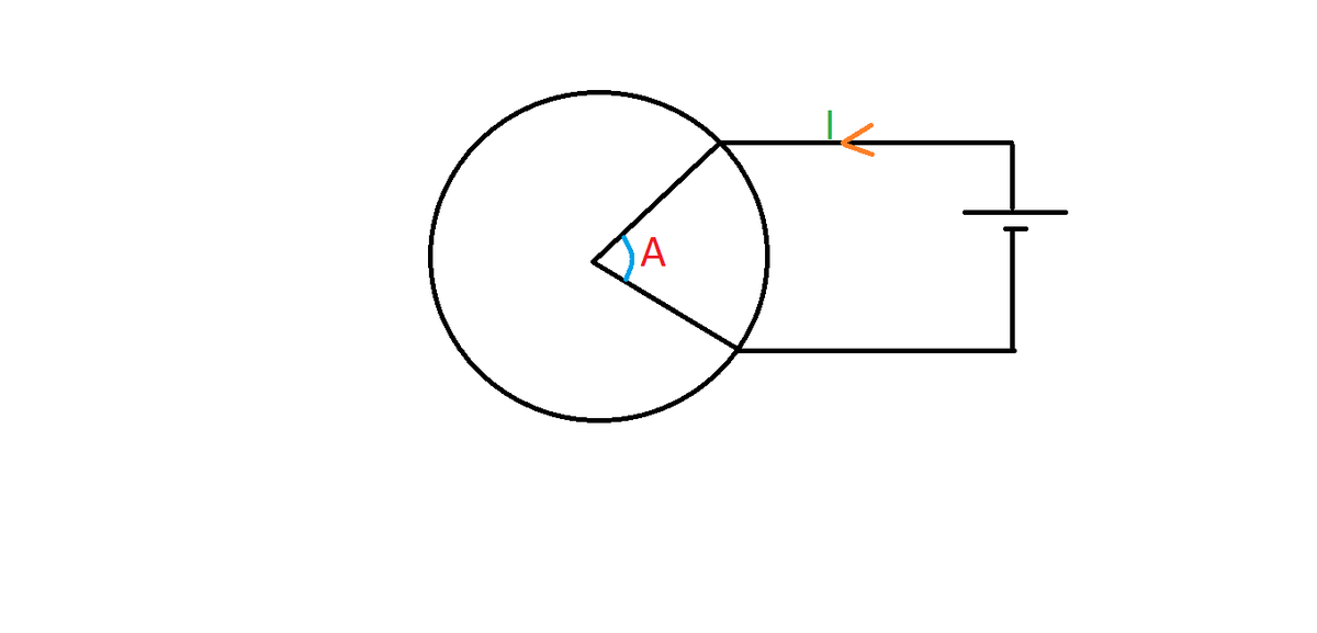
A uniform circular ring conductor is connected to a battery, as shown.
Here the radius of the ring is \(5\) meters and the current \(I\) is \(5\) amperes. If \(\angle A = \frac{\pi}{8},\) find the resulting magnetic field intensity at the center of the ring due to the conductor.
Enter your answer to the nearest integer in microteslas.
Find the magnetic field intensity at the center of a square of side length \(a\) meters carrying a current of \(I\) amperes as shown.
 Due to all sides of the square, the magnetic field at the center is inside the plane of the screen by the right-hand thumb rule. Consider one side of the square as shown.

Now, we know that the magnetic field due to a finite wire at any point is given by
\[\dfrac{\mu_{0} . I}{4\pi d} \big( \sin C + \sin D \big).\]
Here \(C = D = \frac{\pi}{4}\) and \(d = \frac{a}{2}.\) Therefore, \(B = \frac{\mu_{0} I}{\sqrt{2} \pi a}.\)
Since the directions of magnetic field intensities by all sides are in the same direction, the total magnetic field at the center of the square is \(4B = \boxed{\frac{2 \sqrt{2} \mu_{0} I}{\pi a}}\).
A conducting wire of length \(L\) is converted into a regular polygon of \(n\) sides. On passing, a current of \(I\) through the wire produces a magnetic field of intensity \(B\) at the center. Find the value of \(B\).
Details and Assumptions:
- \(I = 5 A, L = 2 m, n = 15.\)
- Give your answer in \(\mu T\) correct to two decimal places.
Ampere’s Circuital Law
We know that the electric field is conservative. Thus, the work done by the electric field along any closed path is zero. In other words, \(\oint \vec{E} \cdot \vec{dl} = 0 \text{ J}.\) But what about the work done in a closed field by the magnetic field? In spite of static magnetic field not being able to do any work on moving charge, we cannot conclude that the line integral of magnetic field along a closed path is zero.
The Ampere’s circuital law states that the line integral \(\oint \vec{B} \cdot \vec{dl} = \mu_{0} \left( i_{\text{total}} \right).\)
Magnetic field created by a long current carrying wire:
Consider a wire as shown (in black) below:
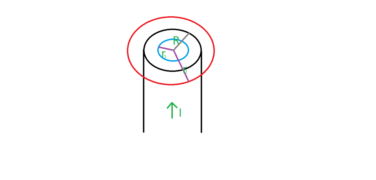
Case-1: For a point inside the wire
Consider an Amperian loop of radius \(r_1\) as shown (in blue) above. Since the current \(I\) is symmetrically distributed over the cross-section of the wire considered, the total current enclosed in the loop is \(\frac{I}{\pi R^2} \times \pi {r_1}^2 = \frac{I}{R^2} {r_1}^2.\) Using Ampere’s circuital law, \(\oint \vec{B} \cdot \vec{dl} = \mu_{0} \cdot I_{\text{enclosed}},\) \[\begin{align} B \cdot 2\pi r_1 & = \mu_{0} \dfrac{I {r_1}^2}{R^2} \\ \\ \Rightarrow B & = {\color{blue}{\dfrac{\mu_{0} I r_1}{2 \pi R^2}}}. \end{align}\]Case-2: For a point outside the wire
Consider an Amperian loop of radius \(r_2\) as shown (in red) above. This loop encloses the total current \(I\) flowing through the wire. So, using Ampere’s circuital law, \[\begin{align} B \cdot 2\pi r_2 & = \mu_{0} I\\ \Rightarrow B & = {\color{blue}{\dfrac{\mu_{0} I}{2\pi r_2}}}. \end{align}\]
Now, clearly for any point on the circumference of the cross-section, the magnetic field produced can be obtained by plugging in \(r_1 = R\) or \(r_2 = R\) on either one of the equations to get \[\color{blue}{\frac{\mu_{0} I}{2 \pi R}}.\]
Force on a Charge Moving in a Magnetic Field
The force on a charge of \(q\) moving with velocity \(\vec{v}\) in a magnetic field of \(\vec{B}\) is given by
\[\begin{align}
\vec{F} & = q \big( \vec{v} \times \vec{B} \big) \\
& = B v q \sin \theta, \end{align}\]
where \(\theta\) is the angle between \(\vec{v}\) and \(\vec{B}.\)
A charge of \(2\text{ C}\) is moving with a velocity of \(2\hat{i} + 3\hat{j} + \hat{k}\text{ m/s}\) in a magnetic field of \(\hat{i} + \hat{j} + 2\hat{k}\text{ T}.\) Find the magnitude of force on the charge.
The force on a moving charge is given by \(\vec{F} = q \big( \vec{v} \times \vec{B} \big):\)\[\begin{align} \vec{F} & = 2 \left( \big(2\hat{i} + 3\hat{j} + \hat{k}\big) \times \big(\hat{i} + \hat{j} + 2\hat{k} \big) \right)\\ & = 2 \big(5\hat{i} – 3\hat{j} - \hat{k} \big)\\ & = 10\hat{i} – 6\hat{j} – 2\hat{k}\\\\ \Rightarrow \big|\vec{F}\big| & = \sqrt{ {(10)}^2 + {(-6)}^2 + {(-2)}^2} \\ & = 140 \text{ (N)}. \end{align} \]
Force on a Current-carrying Wire in a Magnetic Feld
Current is basically continuously moving charge. Therefore, when a wire carrying a particular current in some direction is placed in a magnetic field, it experiences a force given by
\[\begin{align} \vec{F} & = I \big(\vec{L} \times \vec{B}\big) \\ & = B I L \sin \theta, \end{align}\]
where \(I\) is the amount of current passed, \(B\) is the magnetic field intensity, \(L\) is the length of the wire, and \(\theta\) is the angle between the direction of flow of the current and \(\vec{B}.\)
A magnetic field of \(8\hat{k} \text{ T}\) exerts a force of \(8\hat{i} + 3\hat{j} \text{ N}\) on a wire carrying a current of \(2 \ A\) in the \(xy\)-plane. Find the length of the wire.
The force on a current-carrying wire in a magnetic field is given by \(\big(\vec{L} \times \vec{B}\big).\) Let \(\vec{L} = a \hat{i} + b \hat{j}\). There is no component of \(\vec{L}\) parallel to \(\hat{k}\) given current flows in the \(xy\)-plane:\[\begin{align} 8\hat{i} + 3\hat{j} & = 2 \big(a \hat{i} + b \hat{j} \big) \times 8\hat{k} \\ & = 16b\hat{i} – 16a\hat{j}\\\\ 16b &= 8 -16a = 3\\\\ \vec{L} & = \dfrac{-3}{16}\hat{i} + \dfrac{1}{2}\hat{j}\\ \Rightarrow \big|\vec{L}\big| & = \boxed{\dfrac{73}{256}}. \end{align}\]
Force between two infinite current-carrying wires:
Consider two parallel wires of length \(L \to \infty\) in which currents are flowing in the same direction. They are separated by a distance of \(d.\) Let wire 1 carry a current of \(I_1,\) and wire 2 \(I_2.\)
The force due to wire 1 on wire 2 is \(B I_2 L = \dfrac{\mu_{0} I_1}{2 \pi d} I_2 L.\) Therefore, the force per unit length is \(\boxed{\dfrac{\mu_{0} I_1 I_2}{2 \pi d}}.\)
By Newton’s third law, the force due to wire 1 on wire 2 is the force due to wire 2 on wire 1.
By the right-hand thumb rule, we can determine that when the currents are in the same direction, the force between the wires is attractive in nature, while if they are opposite in directions, the force is repulsive in nature.
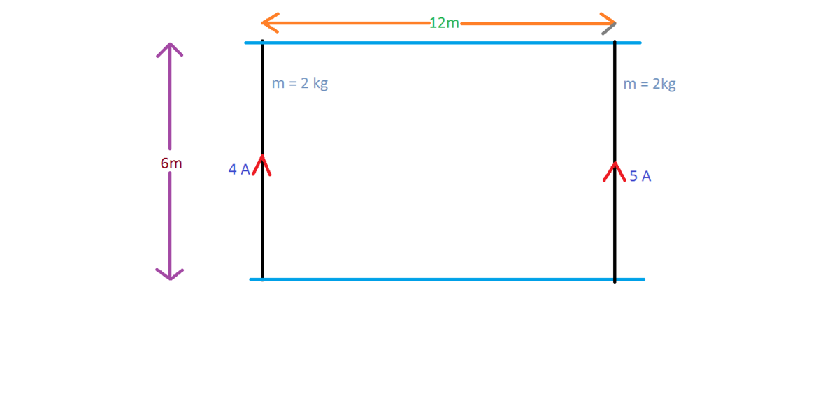
Consider two parallel wires each of mass \(2 \text{ kg}\) connected to two frictionless rails separated by a distance of \(6 \text{ m},\) as shown. One of them carries a current of \(4 \text{ A}\) and the other carries a current of \(5 \text{ A},\) both in the same direction. The wires are free to slide over the rails.
Now, the wires start moving from rest under the effect of their mutual magnetic fields. If the initial distance between the wires is \(12\text{ m},\) find the velocity of the wire carrying \(4 \text{ A}\) when the distance is reduced to half of its initial value.
The answer is of the form \(\alpha \times {10}^{-4} \text{ m/s}.\) Find the value of \(\alpha\) correct to two decimal places.
Motion of a Moving Charge in a Magnetic Field
When a moving, charged particle enters into a magnetic field, a force is exerted on it given by \(q\big(\vec{v} \times \vec{B} \big).\) Thus, it moves along a certain path in the concerned region. When the particles enter the region of magnetic field perpendicularly, the magnetic field only changes the direction of motion and is not capable of accelerating it along the velocity vector, and thus it moves in a circular path. At any other non-zero angle, it follows a helical path.
The closer the angle is to 0, the larger is the pitch; the closer the angle is to \(\frac{\pi}{2},\) the smaller is the pitch. For the sake of simplicity, we only discuss the case when the velocity vector is perpendicular to the magnetic field.
Consider a charged particle of \(+q\) moving with velocity \(\vec{v}\) perpendicularly into a magnetic field of \(\vec{B}\) which is inside the plane of the screen (away from us), as shown.
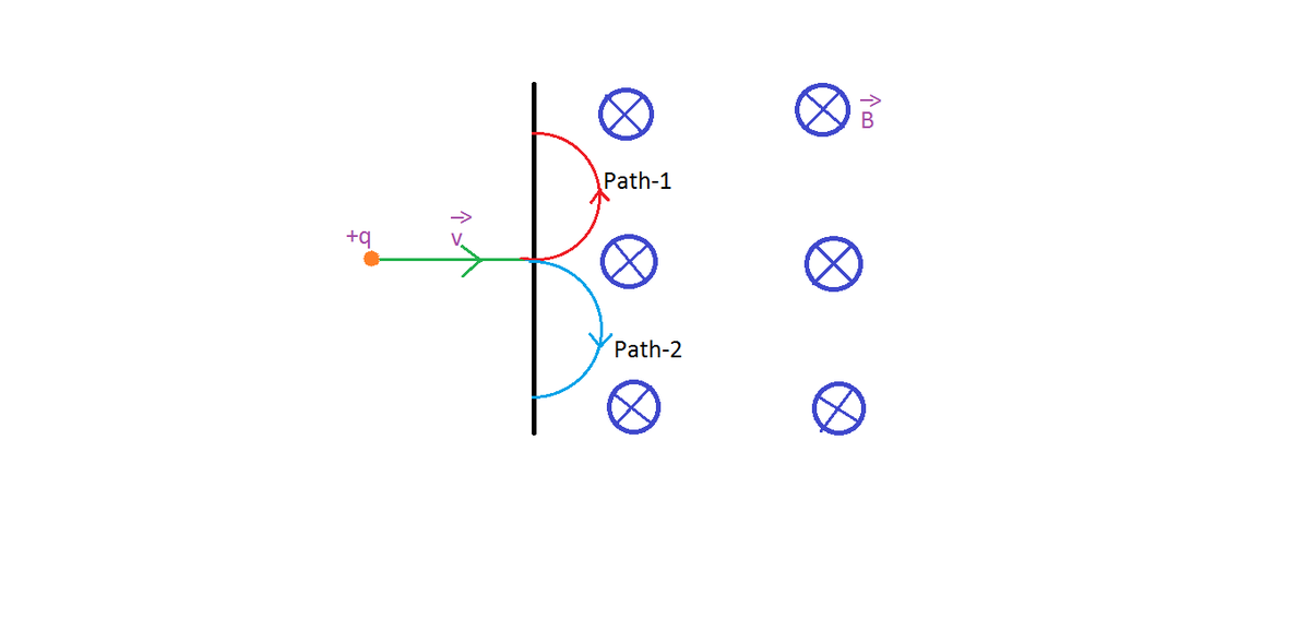
We know that the charge would move in a circle, but which direction would it move in? Would it move along path-1 ( shown in red) or path-2 ( shown in blue)? Since the force acting on the particle is along \(\vec{v} \times \vec{B}\) for a positively charged particle ( for a negatively charged particle it would be the in the opposite direction), the direction of force is \(\hat{i} \times \big(\hat{-k}\big) \ = \ \hat{j}.\) So, the particle would move along \({\color{red}{\text{path-1}}}\) and not path-2. If an electron was considered, then the path would have been path-2.
An alternative method for finding the direction of motion is the right-hand palm rule.
Right-hand palm rule:
Extend your thumb in the direction of the velocity vector. Then extend your other fingers in the direction of the magnetic field vector. If the particle is positively charged, then the direction of motion is in the direction of normal to your palm. The direction is opposite of that in case of a negatively charged particle.
In the above example, extend your right thumb towards the left, and then extend your other fingers towards the screen; since the particle is positively charged, it would move along the normal to your palm which would be facing up. Thus it follows path-1.
Now, let us discuss the radius of the circle it travels along, the time period of revolution, and the distance it travels. The force acting on the particle due to the magnetic field is counteracted by the centripetal force due to which the particle (mass \(m\)) moves with a constant speed. Let the radius be \(r\), then
\[\begin{align} \dfrac{m v^2}{r} & = B v q\\ \Rightarrow r & = \boxed{\dfrac{m v}{B q}}. \end{align}\]
Let the time the particle spends in the field be \(T\), then
\[\begin{align} T & = \dfrac{\text{distance}}{\text{speed}}\\ & = \dfrac{\pi r}{v} \\ & = \boxed{\dfrac{\pi m}{B q}}. \end{align}\]
Clearly, the distance travelled would be \(\text{speed} \ \times \ \text{time} \ = \boxed{\dfrac{\pi m v}{B q}}.\)
A particle of mass \(5\text{ g}\) and charge \(3\text{ C}\) enters into a region containing a magnetic field of intensity \(50\text{ T}\) with a velocity of \( 2\text{ m/s},\) making an angle of \({60}^{\circ},\) as shown. Find the radius of the circle it travels along in the region.
 The component of velocity which is responsible for the circular path is \(2 \sin{{(60)}^{\circ}} = \sqrt{3}\text{ m/s}.\) Now, using the formula for radius \(\frac{m v}{B q},\) we get
\[\begin{align} R & = \dfrac{ 5 \times {10}^{-3} \times \sqrt{3}}{50 \times 3}\\\\ & = \boxed{5.77 \times {10}^{-4} \text{ m}}. \end{align}\]