Simple Circuits
A circuit is the path that an electric current travels on, and a simple circuit contains three components necessary to have a functioning electric circuit, namely, a source of voltage, a conductive path, and a resistor.
Circuits are driven by flows. Flows are ubiquitous in nature and are often the result of spatial differences in potential energy. Water flows downriver due to changes in height, tornadoes swirl due to gentle temperature gradients, and sucrose flows from the leaves of trees to their distal parts due to differences in water potential. Even life itself is due to a clever hack by which living organisms serve as a conduit for the flow of solar energy. Perhaps then it is no surprise that electronic devices (certainly the one you're reading this on now) are driven by flows.
 Water flows over a cliff as a light snowfall returns evaporated water to Earth.
In a simple circuit, voltage flows through the conductive path to the resistor, which does some work. Resistors--things like light bulbs, speakers, and motors--and electric circuits power these devices to do the work that their makers wanted them to do.
Contents
River-Dam Analogy
Flows and circuits can be illustrated via analogies of water, rivers, lakes and dams. If there are two lakes, with a trench dug to connect them, and both lakes have water at the same height \(h_1=h_2\), then the water in the trench will not flow in either direction. There isn't anything driving the system. A given parcel of water has the same potential energy and feels the same atmospheric pressure whether in one lake or the other, so there can be no net transport of water.

If this changes, and the height of the water in one lake is greater than the other, e.g. \(h_2 > h_1\), then water will flow. Now, the pressure on the trench from the water in the higher lake is greater than the corresponding pressure from the lower lake, and hence water should flow out of the higher lake, through the trench, and into the lower lake. If it were possible to keep the water level in the two lakes constant, for instance by replacing the water that leaves the high lake, and removing the water that enters the low lake, then there would be a steady flow of water through the trench.

Moreover the flowspeed could be altered by altering the lakes and trench. If, for example, the trench is widened, or is built out of smooth materials, the flow should quicken, and if the trench is constricted, or filled with rough material and debris, the flow should slow down.
The simplest phenomenological relation consistent with this logic is
\[\text{flow} = \frac{\text{push}}{\text{resistance}}.\]
The push can take many forms including, but not limited to, physical forces, gas and liquid pressures, or differences in potential energy.
In the case of the two lakes, the flow \(J\) is the transport of water from one place to another in response to the push, a difference in pressure \(\Delta p\). The flow can be altered by the characteristics of the flow path, which can be rolled into a descriptive number called the hydraulic resistance, \(\mathcal{R}_H\). For the water flowing through the trench,
\[J = \frac{\Delta P }{ \mathcal{R}_H}.\]
This kind of linear relationship between push and flow is found time and again in many different situations. Often, this kind of relation can get a working model off the ground in systems where very little is known about the detailed workings, and where one might otherwise be paralyzed by details they don't yet understand. However, with a minimal model that can successfully relate measurable bulk properties (like the flow, the push, and the resistance), everyone is in a better position to question the origin of these quantities and build toward a more systematic understanding. Such is the spirit in which the study of electrical circuits began.
Phenomenological Relation - Ohm's Law
Long ago, people noticed that lightning, i.e. charged matter, can move from one place to another en masse. The reason for this is that clouds build up a large asymmetry in charge (i.e. electrons accumulate at the bottom, and the top is left relatively positive) which leaves parts of the cloud highly charged in comparison to other parts of the cloud, nearby clouds, the ground, or even airplanes. This asymmetry creates a large difference in electric potential between the charged region of cloud and other objects. In the case of cloud to ground lightning, the negatively charged bottom region of a cloud has a large electric potential relative to the Earth (which has a net charge approximately equal to zero), on the order of \(10^8\) volts. This is a situation abhorred by nature, and works to relax these gaps in electric potential by flowing charge to balance out the asymmetries.
In the \(18^\text{th}\) century, people began to master the production of batteries, which are devices that can maintain significant gaps of electric potential between two points in space.
When the two points are brought into contact, e.g. by connecting them with a wire, the circuit is "closed" and the battery does work to flow a current, i.e. move charged particles from one end of the wire toward the other. In so doing, the internal potential of the battery is relaxed, just as is the case with the cloud and ground in a lightning strike. Discharging a battery through a loop of wire isn't all that useful, but a battery can be used to drive current through an electrical circuit such as a lightbulb, a circuit-board, a ceiling fan, or a sound system.
When electric potential, i.e. voltage, of a given magnitude is maintained over the terminals of a device, a current will flow through the device. The strength of this current has a linear relation \(V \sim I\) to the applied voltage. The device terminal connected to the positive end of a \(V\) volt battery is kept at high potential (\(V\) volts relative to the negative end), and the terminal connected to the negative end is kept at low potential \((-V\) volts relative to the positive end\().\) The greater the gap in electric potential, the greater the current that will flow through the device.
For every device, the ratio \(V/I\) is given by a parameter, called the "resistance," commonly symbolized as \(\Omega\). If the same voltage is applied to two devices, and one flows half as much current as the other, the device with half as much current is said to be twice as resistive as the other. This resistance is perfectly analogous to the hydraulic resistance from the thought experiment of changing the flow of water in the trench by smoothing its surface \((\)increasing flow, decreasing \(\mathcal{R}_H)\) or filling it with heavy debris \((\)decreasing flow, increasing \(\mathcal{R}_H).\) This relation can be expressed as
\[V=IR,\]
the so-called Ohm's law of circuits, yet another manifestation of the phenomenological push-flow relationship described above.
Units of Resistance
It's now possible to make some observations about the nature of \(R\), the circuit resistance. Rearranging Ohm's law shows \(R = V/I\), i.e. the resistance of a circuit is the cost in voltage to achieve a current of magnitude \(I\) through that circuit. The physical units of the volt are energy per charge, i.e. joules per coulomb \((\text{J}/\text{C})\) in the SI system. The unit of current is simply charge per unit time, i.e. coulomb per second \((\text{C}/\text{s})\) in the SI system, also called amperes, written as \(A\) or "amp". Thus, the units of resistance are \(\text{Js}/\text{C}^2\), commonly called the Ohm \(\Omega\).
Remain in light

Suppose a floor lamp which is rated at a resistance of \(5\Omega\) requires a current of 70 Amps to properly function. What must be the difference in voltage between the prongs of the plug, as provided by the wall?
Because the current that is drawn from the wall obeys Ohm's relation, we can say that \(V_\text{plug} = IR_\text{lamp}\), and thus \(V_\text{plug} = 350 \text{ volts}.\) \(_\square\)
Resistors in Series
For any simple system, finding V, I, or R is straightforward when given the other two factors, but it gets more complicated when a power source drives multiple devices in series. Series means several devices connected end-to-end, with the positive terminal of one device connected to the negative device of the next, just like a set of Christmas lights. Because the devices flow into one another, and charge is conserved, any current that flows into the first device must flow out from the last device, i.e. the current through every device is the same. Devices in series are like water floating down a river: the river can twist, turn, contract, and expand, but the amount of water flowing by any given cross section per unit time must be the same at all points along the river, i.e. \(v_1A_1=v_2A_2\). If this were not so, water would build-up at points along the river and would overflow the banks.

Thus in the circuit above, \(i_1=i_2=i_3\), or since each resistor obeys Ohm's law
\[I=\frac{V_1}{R_1}=\frac{V_2}{R_2}=\frac{V_3}{R_3}.\]
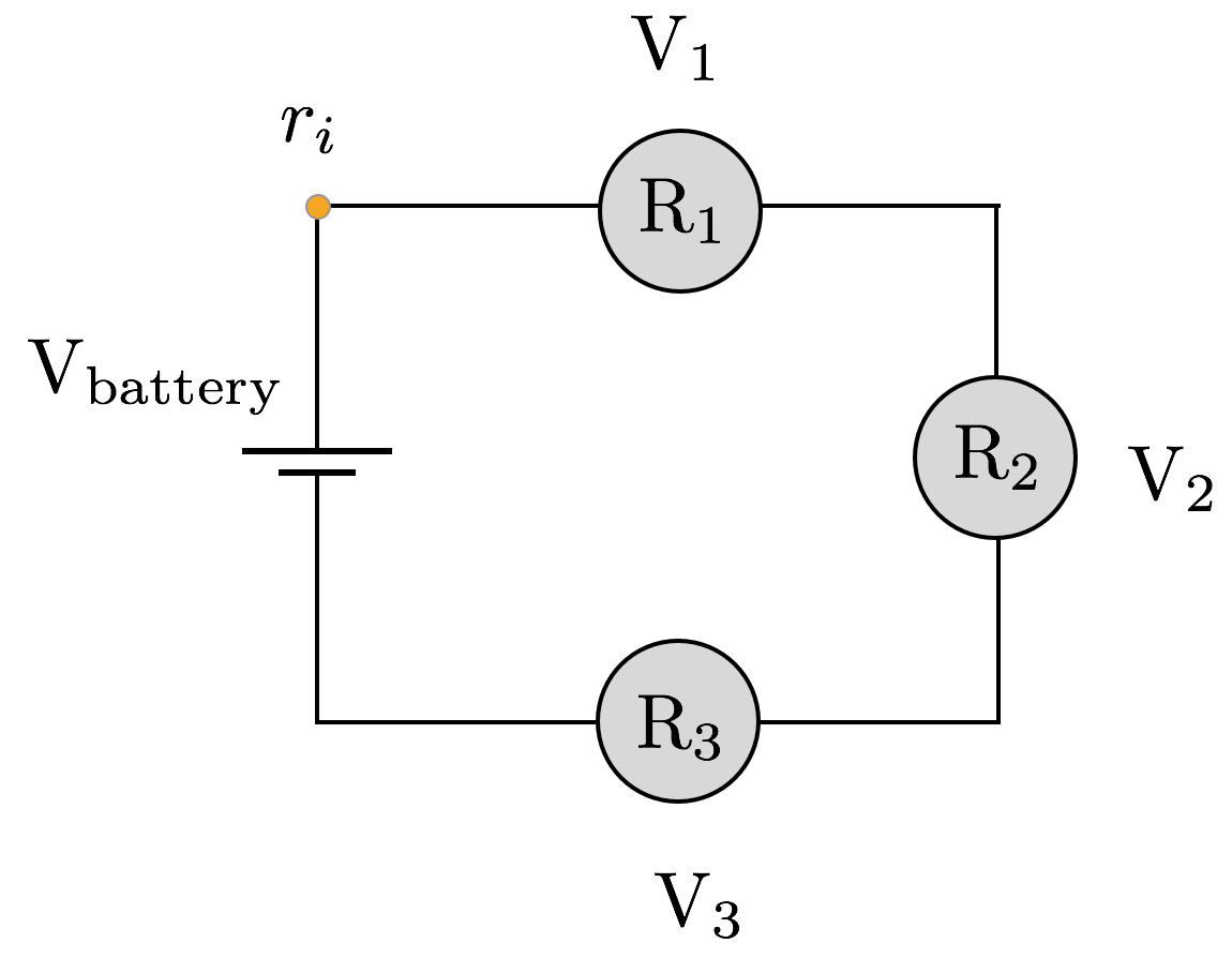
Now, the left side of the orange bulb is connected to the positive terminal of the battery, and the right side of the green bulb is connected to the negative terminal of the battery, which means that the sum of the voltage drops across the three resistors is equal in magnitude to the voltage drop across the battery, i.e.
\[V_\text{battery} = V_1+V_2+V_3.\]
This is the physical principle.
Hence,
\[\begin{align} V_\text{battery} &= V_1+V_2+V_3 \\ &= IR_1 + IR_2 + IR_3 \\ &= I\left(R_1+R_2+R_3\right)\\ &= IR_\text{eff}. \end{align}\]
Therefore, a circuit consisting of three bulbs in series is equivalent to a single bulb with resistance equal to the sum of the individual resistances. This proves the general result for resistors in series.
Resistors in series
The effective resistance of resistors \(R_1,\ldots,R_N\) in series is equal to
\[R_\text{eff} = \sum_i R_i.\]
While arranging circuit elements in series has some attractive features like uniform current, ease of introducing new batteries, etc., there are major drawbacks to arranging circuit elements in series. For one, introducing any new devices decreases the current flowing through the circuit, and thus reduces the power output of every single device. If multiple devices are connected in series, for instance, your oven, your computer, and your reading lamp, dimming your reading lamp (by increasing its resistance) means less current to your oven and computer. Another is that if one element in the circuit, your TV for instance, breaks, the entire circuit will also break because the electric potential gap is no longer maintained across any device. This is inconvenient for building durable circuitry, where we'd like device failures to be independent of one another.
Some of these drawbacks can be avoided in parallel circuit architecture.
Resistors in Parallel
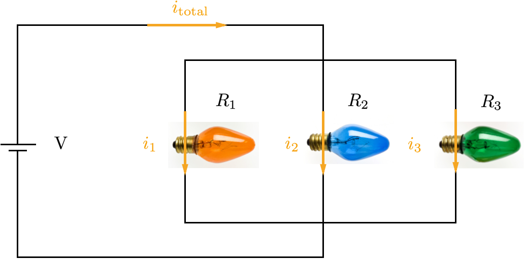
In parallel arrangements, each circuit element is connected to the terminals of the battery independent of the other circuit elements. Because their terminals are each held at the potentials of the battery terminals, the voltage across each device is equal to the voltage across the battery itself. If one of the devices experiences a failure (i.e. the path for current breaks in a given device), the other devices continue to function unabated. Again, we wish to know what happens when a battery drives several devices in parallel, i.e. what is the effective resistance of connecting devices in parallel? Consider the diagram below, depicting a set of resistors in parallel, connected to a battery of voltage \(V\).

The total current coming out of the battery \(i_\text{total}\) splits into three currents \(i_1,i_2,\) and \(i_3\), i.e.
\[i_\text{total} = i_1+i_2+i_3.\]
This is the physical principle.
As each element follows Ohm's law, and each element has the same voltage drop \(V = I_1R_1 = I_2R_2 = I_3R_3\), it follows that \(I_i = \frac{V}{R_i}\). Also, because the total current is conserved:
\[\begin{align} I_\text{total} &= \sum_i I_i \\ &= \sum_i \frac{V_\text{battery}}{R_i} \\ &= V_\text{battery} \left(\frac{1}{R_1}+\frac{1}{R_2}+\frac{1}{R_3}\right) \\ &= \frac{V_\text{battery}}{R_\text{eff}}. \end{align}\]
Thus, the effective resistance of resistors in parallel is given by the inverse of the sum of the inverse resistances.
Parallel resistance
The effective resistance of a set of resistors \(R_1,\ldots,R_N\) in parallel is given by
\[R_\text{eff} = \left(\sum_iR_i^{-1}\right)^{-1}.\]
Infinite ladder of resistors

Calculate the resistance between points \(V_+\) and \(V_-\) in the diagram above.
Studying the circuit diagram, we see that starting from point \(V_+\), the current encounters a single resistor \(R_1\) in series with a branch that has another resistor \(R_1\) in parallel with an infinite ladder. In principle, we can write down new equations every time the circuit makes a new branch, but that will lead to a rather large system of relations to solve. It might be profitable to think about the remainder of the circuit as a black box device of some effective resistance. If we look at the circuit within the black (gray in the diagram below) box, we notice that it is an exact copy of the overall circuit. Of course, it is missing the first bit of circuit that falls outside the gray box, but this is of no consequence as the ladder is infinite. The difference is analogous to subtracting 1 from \(\infty\), and there is no difference between \(\infty\) and \(\infty-1\).

If we call the resistance of the gray box \(R_\text{ladder}\), we have the following expression for the overall resistance:
\[R_\text{ladder} = R_1 + \left(\frac{1}{R_1}+\frac{1}{R_\text{ladder}}\right)^{-1}.\]
Multiplying through by \(\left(\frac{1}{R_1}+\frac{1}{R_\text{ladder}}\right),\) we have
\[\frac{R_\text{ladder}}{R_1} + 1 = \frac{R_1}{R_\text{ladder}} + 2. \]
Simplifying, we find the quadratic equation
\[R_\text{ladder}^2 - R_1R_\text{ladder} - R_1^2 = 0,\]
which yields the solution \(R_\text{ladder} = R_1\frac12\left(1+\sqrt{5}\right) = R_1\phi\), where \(\phi\) is the golden ratio.
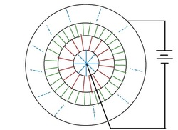
 In the image, the black lines are connecting wires and colored lines are resistors of \(1\, \Omega\) each. The first circle contains 8 resistors, the second one contains 16, the third one contains 32, and so on. There are infinitely many circles of resistors.
A cell is connected between the center and the outermost circle. The equivalent resistance \((\)in \(\Omega)\) between the terminals of the cell is \(k.\) What is \(100k?\)
Assume that the wires (black lines) have negligible resistance.
Kirchhoff's Current Conservation Law
In the parallel resistor discussion above, at the point where the main wire splits into three, the total current is conserved. This principle holds in general, whenever a collection of wires meets at a node. Charge is conserved and all currents must end up somewhere, and therefore the sum of the incoming currents minus the sum of the outgoing currents must equal zero. This is one of the main tools in circuit analysis and is commonly known as Kirchhoff's current law.
Kirchhoff's current law
All incoming currents to a junction of wires must exit the junction:
\[\sum_\text{in}I = \sum_\text{out}I,\]
or if we use the convention that incoming and outgoing currents have opposite signs,
\[\sum_i I_i = 0.\]
Kirchhoff's Loop Law
In the series resistors discussion, the voltage across the battery was equal to the sum of the voltages across the other circuit elements. Further, if an electron moves down a voltage drop \(V\), the electron will pick up the kinetic energy \(q_eV\). Similarly, to bring an electron up a gradient of voltage \(V\), the electron will lose the energy \(q_eV\). Assuming that electrons start from the battery at rest, the energy gained by dropping down the voltage of the battery must equal precisely the energy lost by traversing the resistors.

If this were not the case, starting at some point \(r_i\) in the loop (yellow dot in the above figure), then traveling around the loop, thus changing the potential by the amount \(\Delta V = V_\text{battery}-V_1-V_2-V_3 \), would result in ending up back at \(r_i\) at a higher potential than the journey began with, i.e. point \(r_i\) would have the electric potential \(\Delta V\) relative to itself. Thus, the voltage of the battery and the voltages across the resistors must have opposite orientations, and the voltage around any closed loop must be zero. This is known as Kirchhoff's loop law.
Kirchhoff's loop law
Around any closed loop, the sum of the voltage drops across batteries and devices is zero:
\[\sum\limits_{i\in \text{ loop}} V_i = 0.\]
Determine the resistance in ohms between the points A and B (equivalent resistance) of the circuit shown below. All the values of the resistances are given in ohms.

Find the equivalent resistance between points A and B.

A large number of AA batteries with emf \(\mathcal{E}=1.5\, \mbox{V} \) and resistors with resistance \(R\) form an infinite circuit, as shown in the figure. The internal resistance of the batteries is \(r\). Thevenin's theorem tells us that this infinite circuit can be replaced by a single source with emf \(\mathcal{E}_\text{eq}\), connected in series with an equivalent resistor \(R_\text{eq}\). Determine the equivalent emf \(\mathcal{E}_\text{eq}\) in volts if \(\frac{r}{R}=\frac{1}{2}.\)

In the circuit shown, the current through \(R_1\) is \(4\) amperes.
What is the value of \(V\) in volts?

A battery has an EMF (Electromotive Force ) of \(\displaystyle 6\text{ V}\) and an internal resistance of \(\displaystyle 0.4 \ Ω\). It is connected to a \(\displaystyle 2.6\ Ω\) resistor through a SPST (single pole, single throw) switch.
Find the potential difference between the terminals of the battery when the switch is open and when the switch is closed, in volts.

What is the equivalent resistance between A and B in this circuit?
Note: Approach to the nearest tenth.
What is the equivalent resistance (in Ω) between \(1\) and \(3\) in this circuit, to 2 decimal places?


