Resonant circuits
Resonance occurs in a circuit when the reactances within a circuit cancel one another out. As a result, the impedance is at a minimum and the current is at a maximum. Mathematically, the condition for resonance is
\[X_L = X_C.\]
Resonance allows for the maximum power output of an RLC circuit.
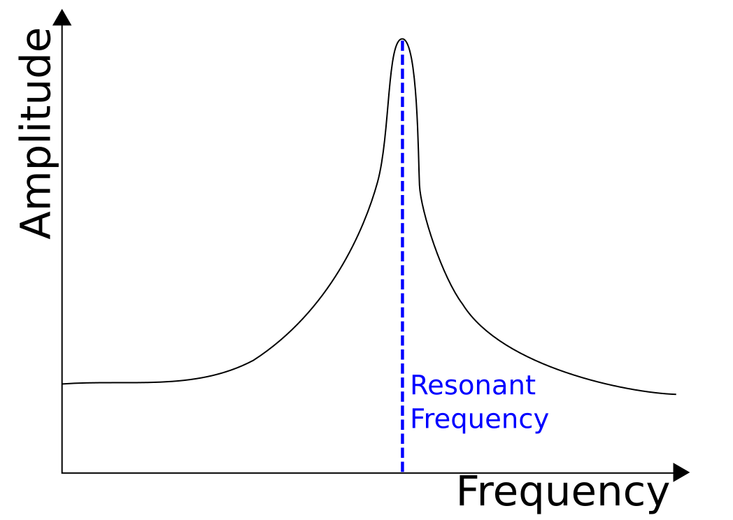
 The current in a circuit peaks at the resonant frequency.
LC Circuit Resonance
Find the resonant frequency of an LC series circuit.
Resonance occurs when the reactance of the inductor is equal to that of the capacitor:
\[\begin{align} X_L &= X_C\\ \omega L &= \frac{1}{\omega C}\\ \Rightarrow \omega &= \frac{1}{\sqrt{LC} }. \end{align}\]
This is also the resonant frequency for an RLC series circuit. \(_\square\)
What is the period of an LC series circuit with inductance \(L = \frac{25}{\pi^2} \text{ H}\) and capacitance \(C = 4 \text{ F}?\)
RLC Circuit Resonance
Resonance of an RLC circuit refers to the condition when the voltage across the inductor is the same as the voltage across the capacitor, or \({ V }_{ L } = { V }_{ C}\). As a result, the EMF of the battery is entirely consumed by the resistor and the current achieves its maximum value.
The basic condition for resonance can be easily derived. Since \({ V }_{ L } = { V }_{ C}\),
\[\begin{align} I{ X }_{ L }&=I{ X }_{ C }\\ L{ \omega }_{ r }&=\frac { 1 }{ C{ \omega }_{ r } } \\ { \omega }_{ r }&=\frac { 1 }{ \sqrt { LC } }. \end{align} \]
Here \({ \omega }_{ r }\) represents the resonant frequency of the circuit, or the frequency of the applied voltage that causes a condition of resonance. Since \({ X }_{ L }={ X }_{ C }\), from the formula for impedance of the circuit, we can easily derive the relation that \(Z=R,\) or in other words, the impedance of a circuit in case of resonance is minimum, or conversely, the current in the circuit is maximum. \(_\square\)
This property of resonant circuits is used amazingly in television and radio sets. Quite basically, such a device can be viewed to consist of an LCR circuit in it. When it receives an electromagnetic signal of some frequency, this signal is converted into an electrical signal which tends to be the AC source for the circuit. Now, for every channel, there's a particular configuration of inductor and capacitor used. So, if the received frequency matches with resonant frequency for that particular channel, then the current in that circuit goes to maximum and the signal is said to accepted.
On the other hand, if it does not match the resonant frequency, then the current stays less than the maximum current and the signal is said to be rejected or denied.
An RLC circuit with components related by \(R=\sqrt{\frac{L}{C}}\) is tuned to half of its resonant frequency. What is the ratio of the current to the maximum current?
ELI the ICE Man
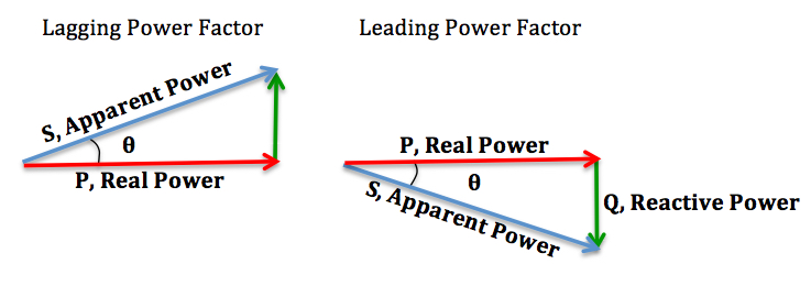
ELI the ICE man is a mnemonic to determine if an RLC circuit is mainly inductive or capacitative. If voltage \(E\) leads current \(I\), the circuit is inductive; if \(I\) leads \(E\) the circuit is capacitative.
 ELI the ICE man is a mnemonic used to remember the relationship between the inductor and capacitor in an RLC circuit. [1]
Power at Resonance
Power in a resonating LCR circuit
We know that the average power of any LCR circuit can be given by \(\bar { P } ={ V }_\text{rms}{ I }_\text{rms}\cos { \phi }. \)
But, for a circuit in which the inductive and capacitive reactance are equal, it can be easily inferred that \(\phi=0\), or \(\cos { \phi }=1\). Plugging this value in the formula, we get
\[\bar { { P }_{ r } } ={ V }_\text{rms}{ I }_\text{rms}.\]
Moreover, since \(Z\) attains its minimum, the current in the circuit \({ I }_\text{rms}\) attains its maximum. Hence, real power in case of a resonating circuit is maximized.
You are ready for your next vacation to a land of peacefulness. The only thing between you and your destination is a shameless metal detector that requires you to walk through it without making it go beep!
You took all the articles off but forgot your watch, and as soon as you walked in, the alarms went off and you are required to walk through again, removing your watch this time. You're good to go and you enter your airplane where you sit down and work out the incident at the airport.
You do know that the metal detector is just a simple application of an LCR circuit. The next piece of info you know is that the sound alarm that blared off was most likely a basic one which requires an RMS current of \(10\text{ A}\) to go off.
Consider the LCR circuit to be made up of a sound source of resistance \(5\, \Omega,\) an ideal inductor of \(2\text{ mH},\) and an ideal capacitor of \(20\text{ pF}.\)
All you need to do is to work out the angular frequency of the current that your watch generated, i.e. \(\omega\) and the RMS value of the alternating voltage for the circuit, i.e. \({V}_\text{rms}.\)
Submit your answer as \(\frac {\omega} {{10}^{7}} + {V}_\text{rms}.\)
References
- Wikieditor4321, . Lagging-leading. Retrieved June 29, 2016, from https://commons.wikimedia.org/wiki/File:Lagging-Leading.jpg