Series and Parallel Capacitors
Given the specific geometry of a capacitor, one can compute the capacitance directly from Gauss's law. However, in most practical situations, the exact geometry is not specified. Rather, one is given the capacitance of several different capacitors and asked about their collective behavior when connected in a specified way.
Many different types of connections are possible. As with resistors, two commonly encountered configurations for capacitors are the parallel and series configurations.
Capacitors in Parallel

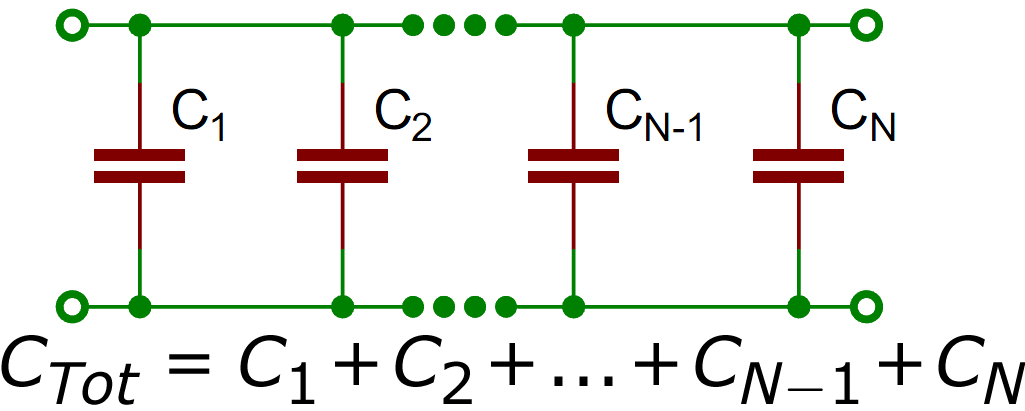
As is the case with resistors, the two terminals of every capacitor in a parallel configuration (as shown above) are connected with each other. The result is that each capacitor is held at the same potential \( V \). If the \( i^\text{th} \) capacitor has charge \( Q_i \) and capacitance \( C_i \), then it follows that \( Q_i = C_i V \) and thus
\[\begin{align} \sum_i Q_i &= \sum_i (C_i V) \\ Q_{\text{tot}} &= \left( \sum_i C_i \right) V. \end{align} \]
Given some potential \( V \), the entire array of capacitors in parallel attains some total charge \( Q_{\text{tot}} \) with a constant of proportionality \( \sum_i C_i \).
In essence, the array behaves as if it were a single capacitor with capacitance \( C_\text{eff} \). For this reason, capacitors in parallel are said to have an effective capacitance given by \( C_\text{eff} = \sum_i C_i \). In other words, if one were only able to measure the total charge across the array \( Q_\text{eff} \) and the potential \( V \), it would be impossible to distinguish between a single capacitor of capacitance \( C_\text{eff} \) and a configuration of capacitors with effective capacitance \( C_\text{eff} \).
What is the effective capacitance of two \( 2 \, \text{nF} \) capacitors in parallel?
The effective capacitance is given by
\[ 2 \, \text{nF} +2 \, \text{nF} = 4 \, \text{nF}. \]


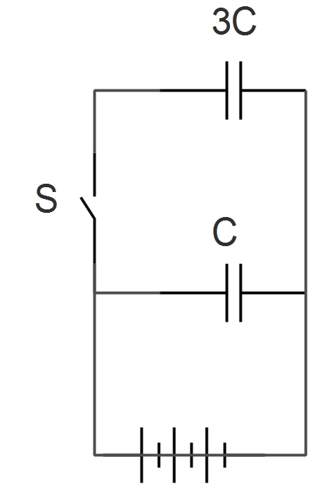
Two identical parallel plate capacitors are connected to a battery with the switch \(S\) closed. When \(S\) is opened and the free space between the capacitors is filled with a material of dielectric constant \(K\), the ratio of the total electrostatic energies stored in both capacitors, after and before the introduction of the dielectric, is \(\text{__________} \).
Capacitors in Series

With capacitors in series, the corresponding terminals of all of the capacitors are no longer connected together. Rather, the terminals are connected in succession, one right after the other, in a chain as shown above. The net effect is that all of the capacitors must carry the same charge. To see why, consider what happens between successive capacitors: if the charge on one capacitor "plate" is \( +Q \), then the charge on the plate connected to that plate must be \( -Q \).
Thus, while the potential difference across each capacitor in series may be different depending on its geometry, the charge across each of them must be the same. As a result, \( Q / C_i = V_i \), and
\[\begin{align} \sum_i \frac{Q}{C_i} &= \sum_i V_i \\ Q \sum_i \frac{1}{C_i} &= V_\text{tot}. \end{align}\]
Given some total potential \( V_\text{tot} \), the entire array of capacitors in series attains some charge \( Q \) across each capacitor with a constant of proportionality \( \sum_i \frac{1}{C_i} \). Thus, the effective capacitance \( C_\text{eff} \) is given by
\[ \frac{1}{C_\text{eff}} = \sum_i \frac{1}{C_i}. \]
What is the effective capacitance of two \( 2 \, \text{nF} \) capacitors in series?
The effective capacitance is given by
\[ \frac{1}{\frac{1}{2 \, \text{nF}} + \frac{1}{2 \, \text{nF}}} = 1 \, \text{nF}. \]

 Capacitors in series and parallel
Each capacitor in the above diagram has capacitance \(C\). What is the equivalent capacitance?
